TriField is a CraigTAVS trademark and the design is copyright (free without permission for non-commercial use).
This hack provides true hemispheric stimulation, extremely interesting peripheral stimulation possibilities and a whole different range of visuals. Suitable for open- or closed-eye use.
As shown, the glasses will work with Rev 3 Procyon or Kasina as 1xRGB (no left/right control). If you wish to sacrifice Kasina glasses, then a full 2xRGB version can be made following the same principles – probably interesting but unlikely more useful.
With the Procyon full control will only be available via the Procyon native synthesizer/editor, otherwise you will have to decide on what 2-3 mapping to use with AudioStrobe – the most directly useful is to drop the blue and use standard red/green AS. Kasina opens up SpectraStrobe.
WARNING: This is not an easy hack and has a high probability of resulting in one or more destroyed pairs of GanzFrames.
You will require:
At least one pair of Procyon or Kasina GanzFrames.
For the method illustrated you will need a second pair of GanzFrames.
Temperature-controlled soldering iron with very fine tip – temperature set 250-300C.
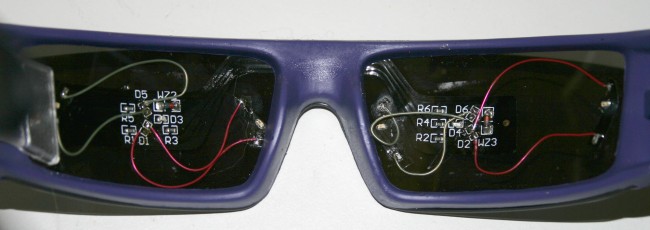
Note: You will probably see my deliberate error in the photos – I subsequently found it highly desirable to move the right red LED to the left and the left green LED to the right. Both sides should have the green-blue-red spacing the same. I found that the red can be further from the blue than the blue from the green. Ideally the red and green should be at the limits of peripheral vision in each eye.
Step 1.
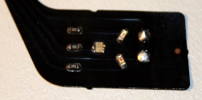
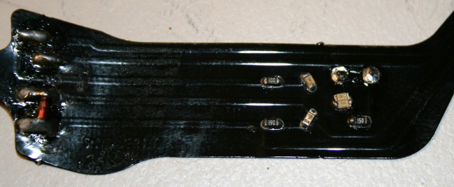
GanzFrames are taped down onto the work surface for convenience. Diffuser removed on right hand side showing unmodified Procyon flexible printed circuit. LEDs are green/top, red/bottom, blue/left. There are a number of GanzFrame variants – you may need a little ingenuity to translate this how-to to match your hardware.
Step 2.
Remove the flexible printed circuit from a second pair of GanzFrames. If you have seriously good eyesight and a very steady hand, this can be avoided by directly wiring the surface mount LEDs – I gave up in great frustration and went the relatively easy way where the second PC provides nice big solder pads.
Step 3.
Remove the diode from the RH section of the PC.
Step 4.
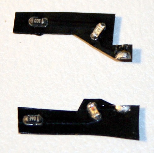
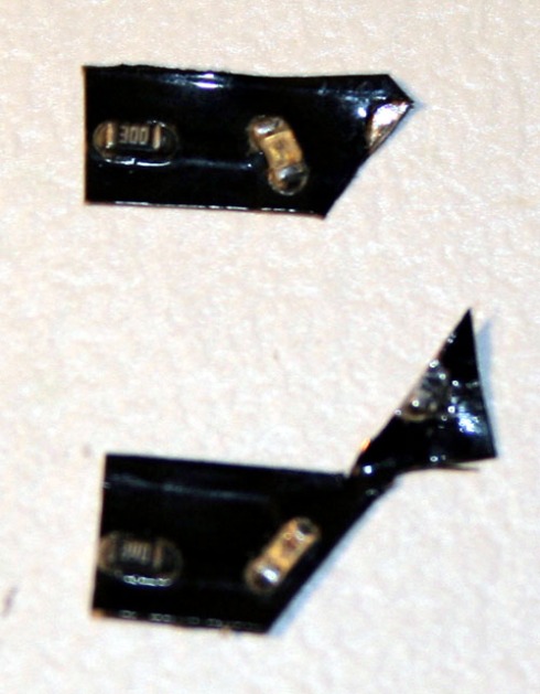
Paying attention to the visible PC tracks, carefully, with knife and scissors, cut the PC as above to provide half a pad from the common end of the diode pad on each piece. The circuit you should end up with on each piece is resistor-LED-common. The resistors can be removed but there is no need to do so.
Step 5.
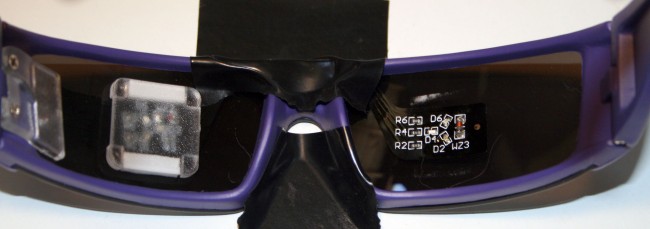
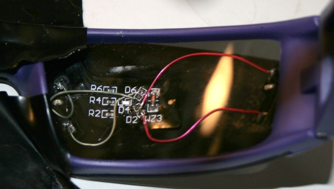
Attach the two fragments of PC as shown. Hopefully there will be sufficient residual adhesive on the PC, otherwise use double sided tape. I chose green/left, red/right out of some sort of port/starboard thinking – whatever, just do the same both sides unless you want to experiment with cross-eye effects.
Remove the green and red LEDs from the main GanzFrames (green shown removed). If you’re doing this the hard way, you will be soldering the subsequent wires directly to the LEDs – note polarity on the back of each LED – good luck!
Step 6.
Using fine wire, connect as shown. Connections on the little pieces are to the end of the resistor nearest to the LED – these resistors are not actually used. I have used much longer wires than necessary because I was using Kynar wire-wrap wire which is an absolute pig to strip in short lengths.
It wouldn’t hurt to test the glasses at this stage.
Step 7.
The process is repeated for the left hand side.
Step 8.
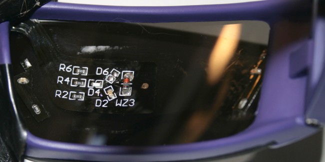
The layout of the left hand end of the flexible PC is different to the right but the circuitry is the same.
Step 9.
This is sort of how the left end gets cut – sorry about the rubbish photo. Same deal as the right hand side.
Step 10.
LEDs removed from main GanzFrame, LEDs on cut PC in place and wired. Oh how I wish I had the eyesight and steady hands of my earlier years!
Step 11.
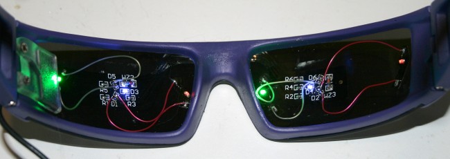
And there they are – both sides wired.
Step 12.
And tested.
Step 13.
By your own ingenium, fabricate a pair of diffusers. These were gnawed out of an old VHS case (remember VHS?). I’m not much of a one for perfectionism in experimental toys – functionality over aesthetics every time.
Step 14.
Fit diffusers – I used thick double sided tape, one layer over the circuit board first then another on the back of the diffuser, not worrying too much about making the diffuser follow the curve.
Good luck!!!
Cheers,
Craig






Comments
Hey Craig,
That is a crazy hard hack… I have worked with the flexible PCBs several times and the diodes and traces are TINY…
But hey I’m game 🙂 I’ve got a few extra pairs lying around…
Thanks so much for the amazing cool hack and detailed instructions.
Scott
May the force be with you!
I think you’ll find the effects sufficiently compelling to justify the effort.
Cheers,
Craig
Hey Craig,
Please explain your motivation for creating a ‘tri-field’ in comparison to L/R brain field stimulation (hemifield) as is normally the case. Is there more reasoning than simply there are 3 LEDs. (probably so)
Also, have you experimented with creating a ‘partition’, isolating the LEDs from one another so as to increase the likelihood of intentional, controllable stimulation?
Best,
Scott
If you are looking at the blue, then the green and red are at the extremes of left/right vision, hence assurance of hemispheric variation.
Haven’t played with many variations of this hack, but the first generation TriField visor has had a few games played with it.
To be honest, it’s all just novelty – I couldn’t claim to have determined any particular use, although theoretically these designs will be good for asymmetrical protocols. Of course, anything novel has the potential to be the stimulus that really does it for you.
I gather you’ve built it? Your first impressions?
Cheers,
Craig
whoah this weblog is fantastic i love reading your articles.
Keep up the good work! You already know, many people are hunting around for this info, you could help them
greatly.
You could definitely see your expertise in the article
youu write. The sector hopes for more passionate writers such as you who
aren’t afraid to mention how thhey believe. Always follow your heart.